Before getting down to Ohm's Law lets reinforce the concepts of electric current and voltage.
Recall that in the previous lesson we learned about charge and the electron. The electron being the fundamental negatively charged particle. An electric current is the average motion of charge in a particular direction. In a metal wire it constitutes the directed drift of conduction electrons through a given cross-sectional area of the conductor. (Picture water flowing through a given cross-section of a pipe.)
The concept of potential difference has also been introduced in the previous lesson. Charged objects set up electric fields about them. The field strength varies with direction and distance from the object depending on the charge distribution of the object. Hence different points in the field may be at different potentials. This potential difference causes the motion of charge. Potential Difference is commonly referred to as voltage. A voltage measurement is always taken between two points. At any one point the pd is 0V. (Analogy: A water pump causes water to flow through a pipe by making the pressure at the source higher than the pressure at the sink. This difference in pressure is what causes water to flow from the source to the sink)
Ohm's Law states that the current flowing through a device is directly proportional to the potential difference applied to the device. The constant of proportion is called the resistance of the device when it is formulated mathematically as,
V = I R
where
V = applied pd. (Voltage V)
I = resultant current. (Amperes A)
R = resistance of material. (Ohms Ω)
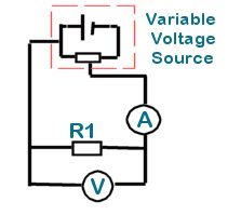
This law can be easily verified by a simple experiment. A length of nichrome resistance wire (or a known value resistor) is connected to a variable DC voltage source through an ammeter. A voltmeter is connected across the resistance wire.
The variable voltage source can be constructed using a potentiometer and a DC power supply.
The variable arm of the POT tap is adjusted to give fixed incremental changes in voltage over a determined voltage range. For each increment the voltmeter and ammeter readings are taken. The readings may be interpreted graphically to determine the resistance value.
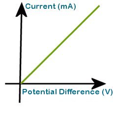
The graph shows the characteristic linear plot for Ohmic conductors. Note that the plot passes through the origin. In the absence of an applied pd there is no current flow.
The resistance of the conductor is the inverse of the graph's gradient. If pd is plotted against current the the resistance can be read directly as the gradient.
Let's look at some actual values to fully appreciate this process.
The voltage was varied from -5V to 5V and measurements taken in increments of 1V
| Voltage (V) | -5 | -4 | -3 | -2 | -1 | 0 | 1 | 2 | 3 | 4 | 5 |
| Current (mA) | -2.00 | -1.61 | -1.19 | -0.80 | -0.40 | 0.00 | 0.40 | 0.80 | 1.2 | 1.60 | 2.01 |
A graph of Voltage vs. Current is plotted using the acquired data

The gradient of the graph is measured to give a resistance of 2.5Ω.
( y = mx, where m is gradient corresponds to V = I R)
A current of 5mA flows through an Ohmic conductor which has a pd of 15V applied across it. What is the resistance of the conductor?
Using V = I R
Transposing, R = V/I
where I = 5mA and V = 15V
gives R = 3kΩ (Normally written
simply as 3k)
What current will flow through a resistor whose resistance is 4.7k when a voltage of 12V is applied across it?
Using V = I R
Transposing, I = V/R
where V = 12V and R = 4.7k
gives I = 2.55mA
What is the voltage across a conductor whose resistance is 10Ω when a current of 500mA flows through it?
Using V = I R
where I = 500mA and R = 10Ω
gives V = 5V
Electric current had been discovered before electrons were known and physicists of the day adopted the convention that current electricity was composed of positive carriers. As a result, in diagrams current arrows show current flowing out of the positive terminals of batteries and into the negative terminals. Electron flow is in the opposite direction.
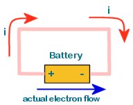 The diagram shows the flow of electric current in a circuit comprised of copper
wire connected to a battery. The red arrows shows the direction of conventional
current while the blue arrow shows the actual direction of flow of electrons.
The diagram shows the flow of electric current in a circuit comprised of copper
wire connected to a battery. The red arrows shows the direction of conventional
current while the blue arrow shows the actual direction of flow of electrons.
Note that electron flow is in the opposite direction of Conventional current flow.
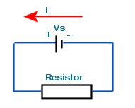
Conventional current flows from an area of high potential to an area of low potential. In more practical terms, we may say that it flows from the positive (+ve) to the negative(-ve).
For example, If point A has a potential of 5V (relative to a specified ground) and point B is at 3V then conventional current will flow from A to B if they are connected by a conductor in a circuit.
If A is at 9V and B is at 4V then conventional current flows from A to B ...
If A is at 7V and B is at 10V then conventional current flows from B to A...
If A is at 2V and B is at -5V then conventional current flows from A to B...
If A is at -10V and B is at -1.5V then conventional current flows from B to A...
If A is at 6V and B is also at 6V there is no current flow between A and B.
All the following problems will have this circuit setup:
An electric circuit comprises a 10k resistor connected across a battery. What current flows through the resistor if the battery has a terminal voltage of 9V and negligible internal resistance?
Answer, I = V/R = 10k/9 = 1.11mA
2.5mA of current flow through the battery which has a terminal pd of 1.5V,. What is the value of the series resistor?
Answer, R = V/I = 1.5/2.5m = 600Ω (0.6k)
What is the maximum voltage that can be applied to a 10Ω resistor if the maximum allowed current through it is 3A?
Answer, V = I R = 10*3 = 30V
What is the total charge passing through a resistor for ten seconds when the applied pd is 5V and resistance is 9k?
Answer, I = V/R = 5/9k = 0.56mA
The current through the resistor is 0.56mA for 10s.
Using, Q = It
Q = 0.56m *10 = 5.6mC
Thus, 5.6mC flows through the resistor in the given period.