
Now that we know Ohm's Law let us investigate the device the has been designed to offer electrical resistance - the resistor.
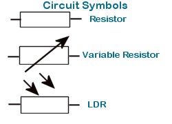
Resistors come in several shapes and forms and are constructed from different materials. There are carbon resistors, wire wound resistors, metalized and variable resistors. Some special types of resistors include Voltage Dependant resistors (VDR) and Light Dependant Resistors (LDR).
Fixed value resistors are typically of the carbon variety. They are made from carbon that has been doped to offer specific resistances. The ease of production makes carbon resistors very cheap and thus they are utilized in many electrical devices.
Resistance wire, which is an alloy that offers fairly high resistivity, is used in the construction of wire wound resistors (these are typically precision resistors). It is also used in filaments and elements.
Variable resistors are also created from resistance wires. These are usually three terminal devices. There are leads connected to both ends of the wire and a sliding contact that allows contact to any section along the length.
Voltage Dependant Resistors are designed to offer resistance that is related to the voltage that is applied across the resistor. It is non-Ohmic. That is, it's resistance value is not constant for different applied voltages.
Light Dependant Resistors change resistance according to the intensity of light they are exposed to. LDR's offer high resistance when the light intensity is low, and low resistance when the light intensity is high.
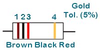
The value of carbon resistors are printed on the resistor as a color code. The code consists of three bands that give the value and a fourth band that gives a tolerance level.
| Color | 1 | 2 | Zeros |
| black | 0 | 0 | |
| brown | 1 | 1 | 0 |
| red | 2 | 2 | 00 |
| orange | 3 | 3 | 000 |
| yellow | 4 | 4 | 0000 |
| green | 5 | 5 | 00000 |
| blue | 6 | 6 | 000000 |
| violet | 7 | 7 | 0000000 |
| grey | 8 | 8 | 00000000 |
| white | 9 | 9 | 000000000 |
Using the color code we can determine the value of the resistor shown above
Brown: 1
Black : 0
Red: 00
Thus the value is 1 000Ω or 1k
If the tolerance band is red then the resistors value will be within 2% of the stated value, gold 5%, and silver 10%. No forth band indicates a 20% tolerance.
For each of the following color sequences determine the corresponding values,
Answers
What color sequences correspond to the following values?
Answers
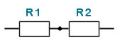 In a series connection devices are connected end to end like in a chain.
Resistors may also be connected in parallel as shown in the diagram below.
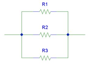
In a parallel connection the two ends of the resistors are connected. (This wording may be misleading. Please refer to the diagram.)
Below we have a series/parallel connection .
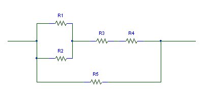
As we can see from the diagram, R1 and R2 are in parallel. R3 and R4 form a series combination. R5 is in parallel with the R1//R2 , R3, R4 subcircuit.
Let us now try to determine the equivalent resistance of series and parallel resistance combinations.
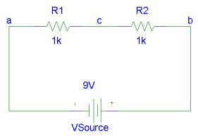
The diagram shows two resistors in series connected across a 9V battery. Suppose that R1 and R2 are replaced by a resistor R whose resistance is such that the current flowing through R would be the same as that which would flow through the R1, R2 series combination in the circuit. This resistor will have a value that is the equivalent of the series combination of R1 and R2.
The voltage across R is related to the current through it according to Ohm's law as follows,
V= I R.
The current through R1 and R2 is also I. Using Ohm's law we get,
VR1 = I R1,
VR2 = I R2
Since the voltage across the series combination of resistors is the same as the source voltage, V
V = VR1 + VR2
Substituting the equivalent resistor for the series combination we get,
I R = I R1 + I R2
I R = I( R1 + R2 )
Or R = R1 + R2
This can be extended for any number of resistors in series.
For n resistors in series, R1 , R2,
R3, ... Rn; the equivalent resistance is R:
R = R1 + R2 + R3 + ... + Rn
Three resistors are connected in series. Their values are 1k, 3.3k and 4.7k. What is the total resistance offered by the series combination?
Answer: R = 1k + 3.3k + 4.7k = 9k
A student needs a 5.1k resistor to complete a circuit but none are available. What series combination of 4.7k, 3.3k, 100Ω, 300Ω resistors do you suggest he use?
Answer: R1 = 4.7k, R2 = 300W,
R3 = 100Ω gives R = 5.1k.
Other combinations are possible but this uses the least components.
What current flows through two bulbs which are connected in series across a 120V power supply? Assume that each bulb has a resistance of 140Ω.
Answer:
The total resistance is R = 2*140 = 280Ω
From Ohm's Law I = V/R = 120V/280Ω = 0.43A
Let us now examine the equivalent resistance of resistors in parallel. Now an equivalent resistor R can replace the parallel combination of R1 and R2 such that the voltage Vab is unchanged and the current through R is the total that would be drawn by R1 and R2.
Thus for R,
V = I R
For R1 and R2
V = IR1 R1
V = IR2 R2
Let us transpose the equations to make current the subject,
I = V/R
IR1 = V/R1
IR2 = =R2
But we know that for the equivalent resistor R the current draw is the sum of the currents drawn by R1 and R2,
I = IR1 + IR2
V/R = V/R1 + V/R2
Or 1/R = 1/R1 + 1/R2
This can be extended for any number of resistors in parallel.
For n
resistors in parallel, R1, R2, R3, ..., Rn; the equivalent resistance is R:
1/R = 1/R1 + 1/R2 + 1/R3 + ... + 1/Rn
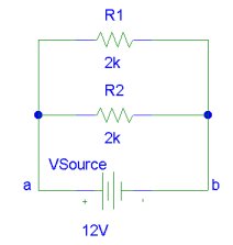
What is the equivalent resistance of two 2k resistance in parallel?
Answer:
1/R = 1/2k + 1/2k = 1k
R = 1k
A student needs a 69Ω resistor and decides to parallel a 100Ω with a 220Ω as a susbstitute. Is that an appropriate solution if the resistance must be within 5% of 69k?
Answer 1/100 + 1/220 = 0.0145
1/0.0145 = 68.75
Since 68.75 is within 5% of 69 that solution is acceptable.
Two 100Ω resistances are connected in parallel across a 9V source. What is the total resistance of the parallel combination of 100Ω resistances? How much current flows through each resistor? What is the total current drain?
Answer:
The equivalent parallel resistance is given by
1/R = 1/100 + 1/100 = 1/50
R = 50Ω
We can arrive at the same result by using the symmetry of the situation. The equivalent resistance of two identical resistances in parallel is half of the resistance.
Since the voltage, V, across the resistors are the same and their resistances are the same; the same amount of current, I, flows through each resistor.
I = V/R = 9/100 = 0.09A
The total current drain is 2I = 0.18A
Let Us simplify more complicated circuits, i.e. circuits that contain series and parallel combinations of resistors.
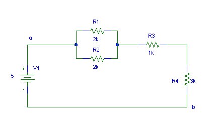
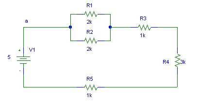
The resistor network between points a and b can be replaced by a single resistor such that it has the same effect in the rest of the network as the original subnet.
We begin by replacing R1 and R2 by their parallel equivalent Ra. Ra = R1.R2/(R1 + R2).
Now Ra, R3 and R4 are replaced by their series equivalent Rb. Rb = Ra + R3 + R4
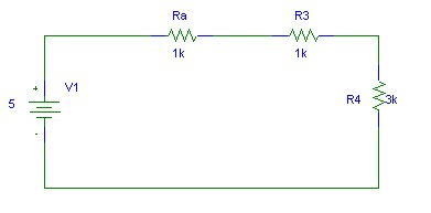
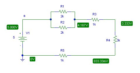
 What
is the voltage across and the current through R5?
What
is the voltage across and the current through R5?
This circuit has the subcircuit between a and b of the previous example inn series with R5. It can be simplified as follows.
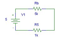
The total resistance R is R = Rb + R5 (6k). Thus the current through R5 (and
Rb) is V1/R = 5/6k = 0.83mA.
The voltage across R5 is V = I.R5 = 0.83mA * 1k = 0.83V
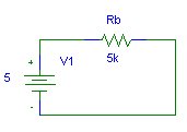
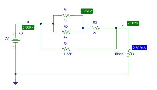
The above schematics shows the results obtain using a circuit simulator. We can immediately see that our answer was correct. When faced with a complex circuit and we only wish to determine voltages or currents for some components it is usually easier to replace other subcircuits (in the network) by simpler equivalents to simplify calculations.
By simplifying the subcircuit between a and b verify the voltage and current for the load resistor in the following circuit. You should get an equivalent resistance Rab ≈ 1k.
Variable resistors may be connected in circuits as rheostats and potentiometers.
When all three terminals are used the device functions as a potentiometer. A given potential is connected across the fixed terminals and a proportion is tapped using one fixed end and the variable arm.
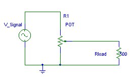
Rheostats are used to increase or decrease the resistance in a circuit. Thus only two terminals are used, one fixed arm and the variable arm.
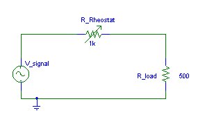 Note
the difference in representation of a POT and a rheostat. (Although the
connection in a rheostat is one fixed and one variable terminal, the schematic
representation is as shown in the diagram. This representation is easier to
draw.)
Note
the difference in representation of a POT and a rheostat. (Although the
connection in a rheostat is one fixed and one variable terminal, the schematic
representation is as shown in the diagram. This representation is easier to
draw.)
Several factors affects the resistance of materials. Here are some of the majors:
But why do all these factors affect resistance? To understand the answer to this question you may find it useful to revisit the lesson on electron theory.
Different materials have different molecular structures. Some materials like metals have conduction electrons that are free to move about the structure Other materials like sand for instance, form structures that keep electrons strongly bonded to their parent atoms. Different metals have different resistivities since atomic radii, proton number and electron energy levels are different.
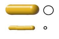
The diagram shows two pieces of a metal wire that are identical except for their cross-sectional area. Which wire do you think will offer a greater resistance to the flow of electric current?
If you consider the water in a pipe analogy you would guess correctly that the thick wire offers less resistance that the thin wire.
A larger cross-section contains a greater amount of molecules and hence more electrons for conduction.
 This
diagram shows metal wires that are identical except for the length. Which would
you expect to offer greater resistance to current flow?
This
diagram shows metal wires that are identical except for the length. Which would
you expect to offer greater resistance to current flow?
Well if it were water flowing through pipes we would get a greater flow rate if the pipe were short rather than if it were long due to more friction in the longer pipe.
I'm sure you've guessed that the short wire offers less resistance. There are less atoms for drifting electrons to bump into in a short section compared to a long section.
How does temperature affect the resistance of a material? Well, for metals and most materials in fact, the resistance rises as temperature rises. This is because temperature affects the motion of the atoms and molecules in the structure. As temperature is increased molecular vibrations and rotations increase in magnitude and frequency. This makes it more difficult for electrons to flow through the material. (Consider, as an analogy, trying to throw a ball through a stationary fan blade and then through a rotating fan blade. Which do you think will be easier?)
Increasing the temperature of silicon actually decreases its resistance. Why do you think this is so? Well although rotational and vibration kinetic energies increase with temperature, the number of charge carriers also increase with temperature for the semiconductor silicon. This factor is the greater contributor giving a negative temperature coefficient of resistivity for silicon.